 |  |
phone: +7 495 1087345 fax: +7 495 1087345 office@trans-service.org |
 |  |  |
 |
 |


Diesel Diagnosis Systems (DDS)
Overview:
Monitoring System Hardware:
System Use:
Back to "Diesel Diagnosis Systems (DDS)"
System Hardware and Installation
The Combustion Engine Monitoring System can be produced in either a Portable or a Stationary version. The major difference between these versions is the cylinder pressure sensor installation. The Stationary version has built-in sensors for continuous engine monitoring. The Portable version has sensors with hand-held adapters, for quick and easy installation on the cylinder head.
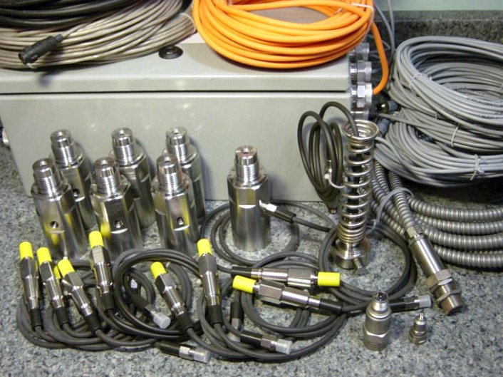
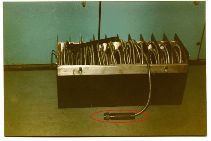
This picture shows the Stationary System, measurement box, cables and our high-quality, extremely reliable Pressure, RPM and Vibration sensors.
Depending on your needs, all cables can be armored. Cable lengths will differ and will be fitted to meet your requirements.
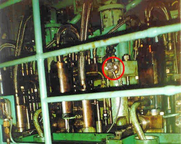
The most important component of the DII Stationary system is the Pressure Sensor (and its connector). It continuously monitors the cylinder pressure in each cylinder, on each revolution.
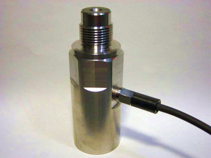
Usually, the sensor is placed between the cylinder head and the indicator valve. The connectors are selected based on your indicator valve type. Using the indicator valve, the sensor passage can be flushed.
The sensor is Swiss made, reliable and extremely long-lasting. It can remain in operation, continuously, for months and even years. Over this lifetime, it is able to function under extremely high temperature conditions.
This sensor is used for the Portable system. It can also be used in the Stationary system for auxiliary engine check-up and for validation of built-in sensors.
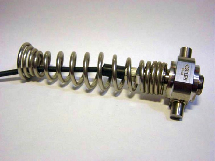
The universal adapter will fit most indicator valves.
Its installation is simple and is usually done by hand.
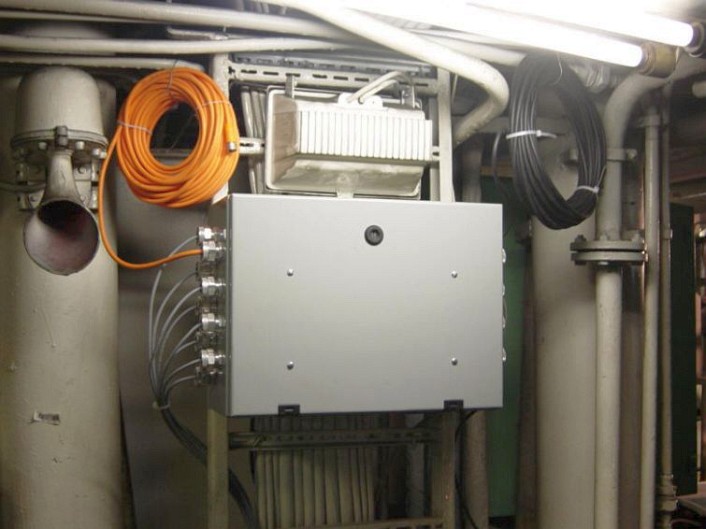
This picture shows an installed Main Measurement Box, in the engine room. A single Measurement Box can handle a single main engine and multiple auxiliary engines.
If a Power Plant has multiple main engines, each main engine is supported by one Measurement Box.
Each Box contains an Uninterrupted Power Supply battery to insure against failures due to external power outages or spikes. Because of the Uninterrupted Power Supply, data can be captured at the Power Plant’s point of failure. Built-in ventilation and filtering systems allow it to operate under extreme temperature, humidity and marine (salt fog) conditions.
In, addition, the system can be extended to write it’s data into a SOLAS approved Voyage Data Recorder.
The system is installed on all major engine types: M-A-N, Sultzer and Wartsila.
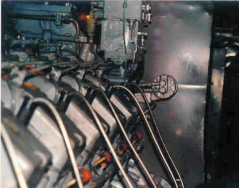
The picture shows the built-in sensors that have been installed on marine vessels, powered by a low-speed M-A-N engine.
To avoid damage, while undergoing engine repair, cables can be armored and sensors can be easily disconnected and reconnected.
The Portable model can handle up to 16 cylinders.
The laptop computer, which receives and processes all measurements, is included with the system. The distance between the computer and the engine can be up to 100 meters.
This Picture shows the portable system installed on a locomotive engine.
Each locomotive was brought in for diagnostics. The installation of the system, including sensors, was done in just minutes.
Immediately after the installation, engineers were able to examine engine conditions and receive system advice for adjustments to be made.
Maintenance personnel can use the Portable system in many different settings.
Because our systems capture all cylinders in a single revolution, they are capable of maintaining more precise cylinder power distribution.
All captured data is archived to enable further analysis.
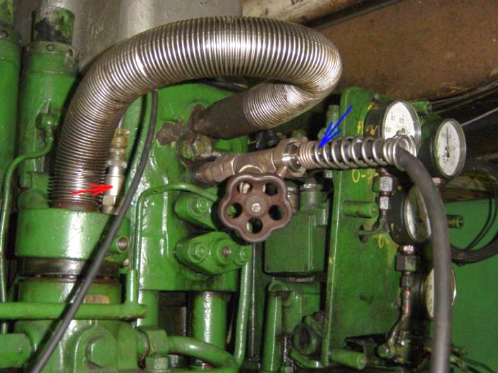
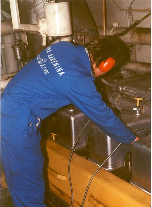
This is an auxiliary engine with a portable gas sensor (indicated by the blue arrow) and a vibration sensor (indicated by the red arrow).
The red, vibration sensor is installed on the fuel pump so that the system can detect the start of injection.
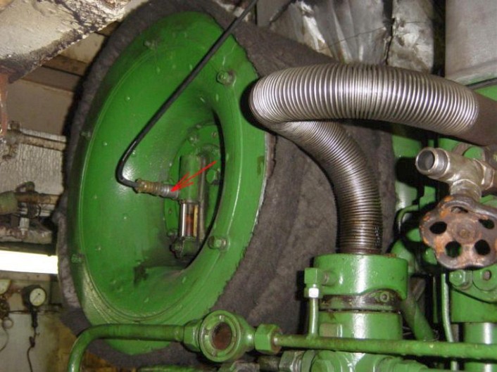
This is the vibration sensor installed on the compressor part of the turbo-charger. The installation was done using a magnetic attachment. The point of attachment must be permanently marked so that all future measurements use a consistent point of reference.
The output will show the amplitude for each frequency. If the amplitude or frequency exceeds any customer-set limits, warnings will be generated.
The data archive allows the comparison of current and prior measurements.
General Information: